mPower™ DC Features
USB, Ethernet
All series come with a USB interface for programming and remote control. USB allows both ModBus and SCPI protocols, as well a general purpose control by the Windows application software, and LabView VI driver.
An Ethernet port is also standard on 300 and 311 Series. While a basic web page is available on port 80, the main purpose of the Ethernet connection is to support remote programming using ModBus TCP, CAN, EtherCat, ProfiNet, and others.

AnyBus Modules
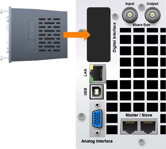
The 311 Series includes an AnyBus port. Shown below is the layout of a 3U units with the AnyBus opening, and a typical module ready for installation (just slide it in).
AnyBus offers multiple field-replaceable modules with connectivity and protocol support for RS-232, Ethernet, ModBus TCP, EtherCAT, CAN, OpenCAN, Profibus, and ProfiNET.
Analog Interface
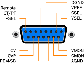
All systems include an analog interface. The analog interface includes 14 control and monitoring signals. Remote control can be enabled/disabled, voltage, current, and power settings can be adjusted, actual voltage and current are monitored, and several are alarms are indicated.
A common use of the analog bus is for switching the dc output on and off (especially useful for the 300 series).
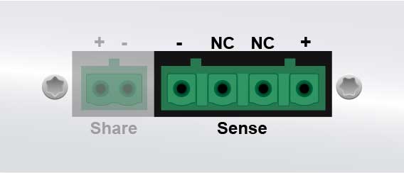
Sense Bus ↑
All models include the Sense bus. The (+) and (-) terminals of this bus are connected to the DC input of the device under test. During constant voltage operation (CV), the adjusted output voltage will be held constant at the load, and not at the power supply’s DC output.
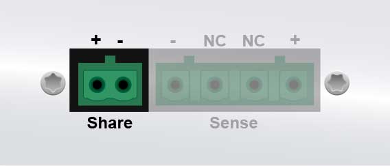
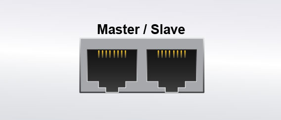
Share Bus ↑
All models include the Share bus. The Share Bus is used to balance a load across parallel units. With the bus connected (daisy chained across all units), output voltage is regulated between all units, and current is shared and managed for load balancing as well.
Expansion Bus ↑
The 311 series features an expansion control bus. This bus improves the operation of parallel units by enabling communication between a control unit and expansions units to share setpoint settings, alarm settings, unit capacities, and more. All systems are controlled from one touch panel.
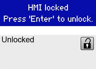
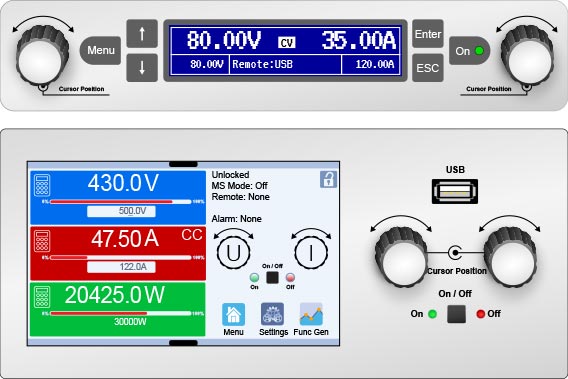
Lockout ↑
All models include the ability to lock the user interface from accidental changes. The lock status is shown on the control panel as seen below (300 Series top, 311 Series bottom). In the 300 Series, the lock is activated with a brief navigation to a menu item. With the 311 Series touch panel, it’s even easier—tap the lock icon in the status panel. Unlocking can require a PIN, or can simply require the acknowledgement of an “are you sure” prompt.
Rotary Controls ↑
All models include rotary controls as part of the user control panel. These are used for changing the voltage, current, and power set values, and other numeric values when shown on the display. When in normal operating mode (not viewing menu options), the knob is pushed in like a button, and this cycles through the numeric places (tenths, ones, tens, etc.). Then the dial is rotated to assign the numeric value (0-9). Each knob is assigned a default parameter to adjust (some user assignment is possible) making quick changes for a series of tests easy and quick.
Profiles ↑
A profile is a collection of all settings and set values. When the system settings and/or set values (voltage, current, power) are adjusted, these changes create a working profile which can be saved to one of the five user profiles. A default profile also exists, which cannot be changed, but can be selected.
The purpose of a profile is to store and recall a collection of set values, settings limits, and monitoring thresholds quickly without having to readjust these manually. This makes it much faster to change among a set of test parameters which are being used repeatedly.