Power Monitoring
A white paper about power distribution monitoring options.
Seeing is Believing
For many power distribution applications, the display and monitoring of power quality and status provides confidence that downstream equipment is getting what it needs. This could be a simple indicator lamp showing the PDU is powered on, or it may involve an array of digital meters to display specific parameters of multiple circuits.
Power monitoring capabilities allow tracking of power quality, available capacity, and simple on/off status of circuits or outlets. Additionally, displays can be used for manual observation or integrated into an overall automated measurement and response system. With some equipment designs, the PDU is not visible to the user, so a method of remotely monitoring this information can be implemented. Since the PDU is a natural focal point of power management, it is the most logical place to integrate some kind of monitoring, and Marway can tailor design to utilize a variety of capabilities.
Common Measurements
The following measurements types tend to fulfill the majority of monitoring applications.
On/Off status can be used to monitor whether a power source is enabled, an outlet is powered or not, or the active choice status of an A/B switch selection. Typically there are only two values, though multiple choices are possible.

Time can be used to measure the cumulative time that the entire PDU or individual circuits have been powered. This is often used to coordinate maintenance scheduling of equipment connected to the PDU.
Voltage at a power outlet, or more commonly, the incoming power source can be measured to ensure facility power is meeting the requirement of downstream equipment.

Current can be measured at one or more points within the system to reveal the total load at the power input, on a branch circuit, or even at an individual outlet. Measuring capacity usage can be useful where downstream loads may vary, and drawing too much current will trip a circuit breaker.


Power is derived from a combination of voltage and current measurements from the same point at the same time. Calculated measurements can include watts, volt-amperes, power factor, and crest factor. Energy factors in time for values such as kilowatt-hours. All of these values are useful for analyzing consumption and efficiency.

Power quality is a developing area of power measurement where some differences in formulas and calculations may still exist among device manufacturers. Generally speaking, power quality is represented by a number of measured and calculated parameters such as flicker, dips, swells, transients, and harmonics among others. These values can be used to define the quality of the power being provided by the facility power source. A power quality meter can be integrated into a PDU, but such equipment is typically a separate device which is temporarily installed for troubleshooting purposes.
Monitoring Methods
It is worth clarifying at this point that the term monitoring is used in many ways. It is often used to describe the combination of both measurement and display, but can also be used to mean just one or the other. For example, measuring voltage and sending the measurement signal into a device without displaying a value is “monitoring” the voltage. This document uses the term in all of its interpretations, and will attempt to be clear when the discussion is specific to measurement or display.
Remote Monitoring Signals
In addition to the panel displays which can be mounted on local or remote panels, it is possible to convey measurements to separately housed monitoring equipment with a variety of remote signals. These are very similar to the signals described in the Power Control document. The difference is the intent. Where a control signal is used to send a command, a monitoring signal is used to indicate a data value. The signal itself may technically be identical in both cases.
A dry contact is the simplest form of remote monitoring interface. A contact closure on a switch or relay is used to signal an on/off or other A/B selection condition. This signal would typically be used with an external control system.
A discrete signal involves sending a fixed voltage or current signal which has only two states, such as 0 Vdc vs. 5 Vdc or 0 mA vs. 20 mA, from the remote panel to the PDU. The signal is received by a digital control circuit or the coil of a relay of an external control system. The design requirements of the sender and receiver must be understood to ensure the signal is compatible with both.
An analog signal is a variable voltage or current, typically 0–10 Vdc or 4–20 mA, used to represent a data value such as line voltage, main input current, or chassis temperature. The signal is wired directly to a panel meter for display, or several of them may be wired to a digital controller to display multiple measurements on a single display.
A communications interface provides a means to transmit multiple measurements using digital controllers. Multiple sensors will be wired into a local controller in the PDU. One or more remote stations will house their own controller. Measurements at the PDU are converted into pre-defined “messages” and sent to remote controllers following a standardized protocol such as RS-232, Modbus, HTTP, SNMP, or others. This form of remote communications offers the richest flexibility of monitoring, but may require the most engineering resources to implement.
Panel Display Options
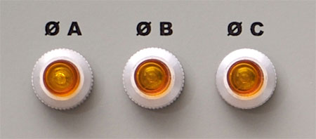
Panel displays are any indicating device mounted to a PDU’s chassis, or to a separate remote panel. The images on the right correspond to the following descriptions.
Indicator lamps are the simplest form of display (unless you count visually noticing the position of a toggle switch). They can be used to indicate the presence of power, the selection status of a switch, or the open/closed status of an interlock.
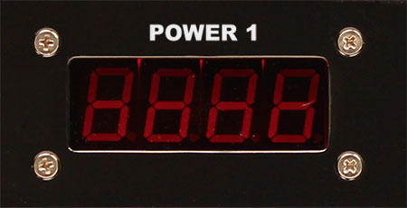
A digital meter provides an alpha-numeric display of a single measured value, though usually only numeric for PDU applications. The sensor is connected directly to the meter for a real-time display of the measurement.
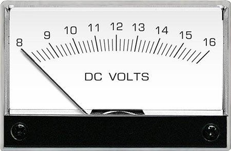
An analog meter uses a movable needle in front of a printed numeric scale to indicate the measured value. Like a digital meter, the sensor is wired directly to the meter.
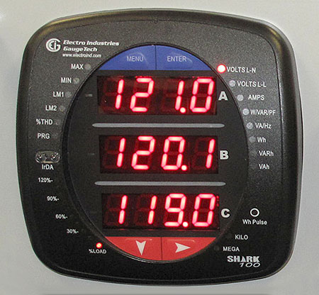
A digital interface or multifunction meter provides for the display of multiple values in one device. Buttons allow the user to choose which value to display. Multiple general purpose devices might be used to cover all possible values, or a single custom device might be used. In either case, these displays are used where there is insufficient panel space for individual displays.
Setpoints and Alerts
Additional important capabilities in monitoring include setpoints and alerts. These features expand on the mere display of data measurements by providing automated responses when conditions are outside desired parameters.
A setpoint is an adjustable value which when exceeded will change the state of an alarm signal. For example, if a maximum main input current is rated for 30 A, a setpoint may be set for 27 A. A panel meter might contain a dry contact which would normally be open (no contact) when the measured current is below 27 A. If the measured value exceeds 27 A, the dry-contact is closed, and the PDU could route a signal through that contact to power either an indicator lamp, or even trigger an alarm speaker to alert a nearby operator. In equipment with advanced digital controllers, setpoints can even be configured to send SMS or email messages as alerts. Setpoints are often used to monitor the high and low limits of an operating range of volts and amperes, though other parameters are also possible.

Advantages to Power Monitoring Integration in Marway PDUs
Ultimately, a reduction in packaging complexity and component redundancy is the root of the following advantages found in the integration of power monitoring features into a PDU:
- reduced space,
- reduced weight,
- reduced cost,
- improved cable management, and
- added convenience.
When creating an integrated solution, Marway can address the unique needs of an application, and optimize the selection of components for power capacity and packaging efficiency.
Marway has specialized in the single-chassis integration of these capabilities to reduce space, weight, and costs, and to improve monitoring capabilities compared to separately housed third-party components. We believe that ultimately it’s the combination of power performance, packaging efficiency, and product quality which keeps our customers coming to Marway to meet their power distribution needs.